# Switch table
```
//-----------------------------------------
//------------TABLE VARIABLES-------------
//-----------------------------------------
uint8_t row[] = { 0, 0, 0, 0, 0 };
const uint8_t rowCount = sizeof(row) / sizeof(row[0]);
uint8_t col[] = { 0, 0, 0, 0, 0 };
const uint8_t colCount = sizeof(col) / sizeof(col[0]);
//---------------------------------------
//--------TABLE DESCRIPTION-------------
//---------------------------------------
const uint8_t buttonNumber[rowCount][colCount] =
{
{0, 0, 0, 0, 0}, //ROW 1
{0, 0, 0, 0, 0}, //ROW 2
{0, 0, 0, 0, 0}, //ROW 3
{0, 0, 0, 0, 0}, //ROW 4
{0, 0, 0, 0, 0} //ROW 5
};
//---------------------------------------
//------------DIRECT INPUT---------------
//---------------------------------------
uint8_t directPins[] = { 99 };
const uint8_t directPinsCount = sizeof(directPins) / sizeof(directPins[0]);
//---------------------------------------
//------------DIRECT OUTPUT--------------
//---------------------------------------
#define enableOutput 0
uint8_t outputPins[] = { 99};
const uint8_t outputPinsCount = sizeof(outputPins) / sizeof(outputPins[0]);
//---------------------------------------
//--------ANALOG DESCRIPTION-------------
//---------------------------------------
#define analogSwitchCount 1
const uint8_t analogButtonNumber[analogSwitchCount] = //ANALOG BUTTONS 1
{ 0 };
const uint8_t analogButtonNumberIncMode[analogSwitchCount] = //ANALOG BUTTONS 2
{ 0 };
```
## Rows and columns
We start by describing the rows and columns; their size and which pins they are connected to.
### `uint8_t row[] = {0,0,0,0,0};`
Insert pin numbers for your rows, starting with first row. Defaults to 5 rows, reduce/increase to whatever you have in your project.
If wired like the board at the top of [3.Wiring](https://github.com/andreasdahl1987/DahlDesignDDC/wiki/3.-Wiring), you'd write it like this:
`uint8_t row[] = {15,14,16,10};`
### `uint8_t col[] = {0,0,0,0,0};`
The same as above. For the example picture this will be:
`uint8_t col[] = {3,4,5,6,7};`
### `uint8_t directPins[] = {99};`
* Only relevant if using direct wiring. List the actual microcontroller input pin numbers that these switches are connected to. The order doesn't matter, this is just used for pulling up the pins. Default is "99", which is just a dummy that fills the array with someting.
As an example:
`uint8_t directPins[] = {2,3,16,15,10,8,9};`
### Direct wiring/shift registers
When using direct wiring or shift registers, the rows and columns aren't actual microcontroller input pins - we'll use dummy-pins instead, which is **"99".**
Any row or column that only has direct wired switches or shift registers on them, should be written as "**99**". The reason we have to use a dummy is that we need to build a matrix in the firmware with the correct size. As mentioned earlier, each switch needs a slot in the firmware matrix to get memory to store switch states, timers for debouncing, etc.
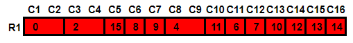
* These examples from [1. Project planning](https://dahl-design.gitbook.io/ddc/1.-project-planning/switch-inputs/non-matrix-switches):
`uint8_t row[] = {99};`
`uint8_t col[] = {99,99,99,99,99,99,99,99,99,99,99,99,99,99,99,99};`
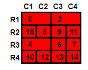
`uint8_t row[] = {99,99,99,99};`
`uint8_t col[] = {99,99,99,99};`
* A hybrid system with the first two rows reserved for direct wired switches could look like this:
`uint8_t row[] = {99,99,4,5,16};`
`uint8_t col[] = {15,10,14,7};`
The pin numbers used here are just examples.
* An extreme example with several bundles of shift registers, matrix wiring and direct wiring in the same project:
Here, the first 5 rows are dummy-rows. But also columns 5-8, since here are only shift registers and/or direct wired switches. In essence, only the matrix wired part (rows 6-8 and columns 1-4) should have real pin numbers, the rest are "99".
`uint8_t row[] = {99,99,99,99,99,4,5,16};`
`uint8_t col[] = {15,10,14,7,99,99,99,99};`
## Button numbers
The reason why I set up my switch table in a spreadsheet is this:

```
const uint8_t buttonNumber[rowCount][colCount] =
{
{20, 0, 4, 5, 6}, //ROW 1
{9, 10, 11, 12, 13}, //ROW 2
{14, 0, 8, 22, 0}, //ROW 3
{16, 0, 7, 18, 0}, //ROW 4
{0, 1, 2, 3, 0} //ROW 5
};
```
You simply copy your switch table to this one. By default it is a 5 x 5 table. Adjust it accordingly. 4 x 7 would be like this:
```
const uint8_t buttonNumber[rowCount][colCount] =
{
{0, 0, 0, 0, 0, 0, 0}, //ROW 1
{0, 0, 0, 0, 0, 0, 0}, //ROW 2
{0, 0, 0, 0, 0, 0, 0}, //ROW 3
{0, 0, 0, 0, 0, 0, 0}, //ROW 4
};
```